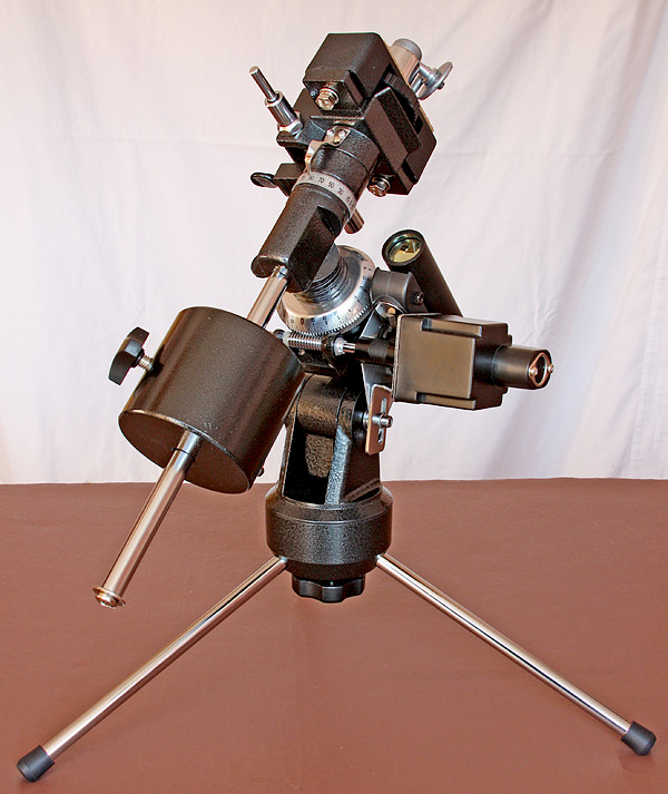
The EQ1 mount is the smallest of the equatorial mounts produced by Synta and marketed by Sky-Watcher and Orion. Available in both tripod mounted and table top form, I went for the latter because I was looking for the minimum set-up for taking on holiday by plane.
The EQ1 doesn’t have the best reputation for stability and tracking ability but I intend using it for widefield imaging with just a camera and camera lens so I will be putting the minimum stress on the system. However, for any kind of imaging, a good polar alignment is a pre-requisite and this mount doesn’t have a polarscope facility so I needed to address this.
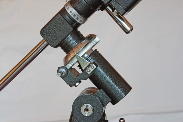
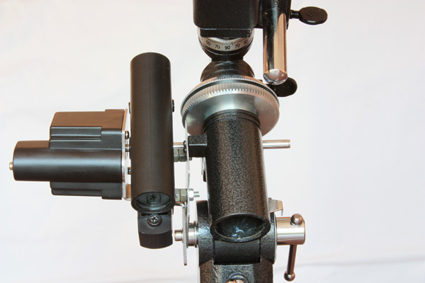
Conventional polarscopes are installed inside the RA axis with a peep hole in the centre of the DEC axis but this would not be possible with the EQ1 so I opted for a side-by-side arrangement. I have no intention of using the setting circles so the mounting pillar for the RA setting circle pointer made for an obvious first mounting point and the mounting bolt for the RA motor made for a second mounting point.
I was given an old air rifle some time ago and it came with a Red Dot Finder (RDF) similar to the ‘ScopeTeknix Universal fit auto-shutdown red dot finder’ and the small size of this device made it ideal for installation in the cramped space available.
The two bolts designed to tighten up the dovetail clamp on the base of the unit made a simple method of attaching the unit to a fabricated aluminium bracket with some spacers to ensure that the unit didn’t foul the RA axis gear. No doubt other solutions could be found for different designs of red dot finder but the key to this project is the simple bracket mounting which acts as a base for the rest of the installation.
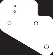
So let’s look at this bracket and how to make it. I used what I had available in my junk box and that just happened to be 1mm aluminium sheet which was ideal because the bolts that originally retained the RA pointer are not very long. I made up a thin cardboard template and mounted my RDF to it. This allowed me to accurately locate the three bolt holes on the mount with a probe. The template included with this article will be a good start for you but remember that you will need to produce your own mounting holes for the RDF that you decide to use as those marked on the template are for my own one.
I covered an area of the aluminium sheet with masking tape and marked the shape of the template on the tape prior to cutting it out with a small toothed hack saw. I filed the rough edges with a small flat file and rounded all the corners for neatness and safety. Finally, I placed the template on top of the bracket and marked the position of the three mounting holes for attachment to the mount.
A pillar drill is ideal for drilling the mounting holes although mine is a rather crude attachment for a standard electric drill, it did the job just fine. A normal electric drill would also work though because the aluminium sheet is thin so it would not be a major problem if the holes weren’t drilled perfectly perpendicular to the bracket.
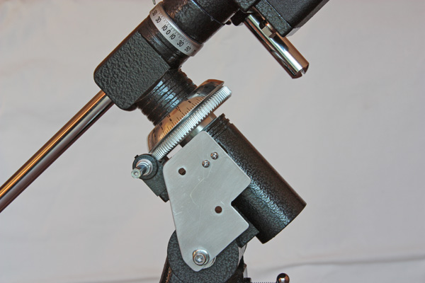
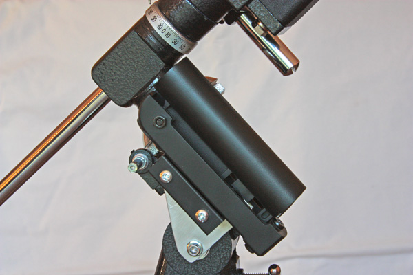
The aluminium bracket can now be bolted to the pillar that originally held the RA Pointer and aligned over altitude axis bolt.
The RDF can now be attached firmly to the aluminium bracket prior to installation of the RA motor.
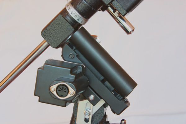
The RA motor has a sprung constant velocity joint and this should be gently slid over the RA shaft and the motor gently orientated until its mounting bracket is also aligned over the altitude axis bolt. The altitude axis bolt can now be installed and tightened to retain the motor and sandwich the aluminium bracket. The RA worm drive can then be rotated until the flat on the shaft is aligned with the grub-screw in the constant velocity joint and the grub screw tightened until it just ‘nips’.